Assembly And Installation Of Hardware
Contents
Test Assembly
After you gathered all the individual parts, we recommend to do a test assembly outside of the machine. This way, you can get the whole system up and running and can still reach all cables and parts easily.
Instead of running the heating of your coffee machine, you can use e.g. a light bulb instead, but any other 120V or 230V consumer works equally.
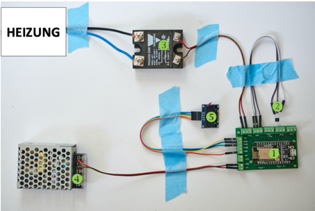
(1=Microcontroller, 2=Temperature Sensor, 3=SSR Relay for Heating, 4=Switching Power Supply, 5=Display, Heizung=Heating)
Setup
Connecting the Temperature Sensor
CAUTION! The TSIC temperature sensor is sometimes delivered with an incorrect data sheet, which shows the wrong polarity.
You should take special precaution when connecting the TSIC 306 temperature sensor. Once they have been connected incorrectly and got supplied with current, they are either destroyed instantly or will at least be damaged and will report incorrect measurements. It is therefore recommended to always have a spare sensor at hand.
- Sensor
VCC: BoardT_SENS3.3V - Sensor
Signal: BoardT_SENSSIG - Sensor
GND: BoardT_SENSGND
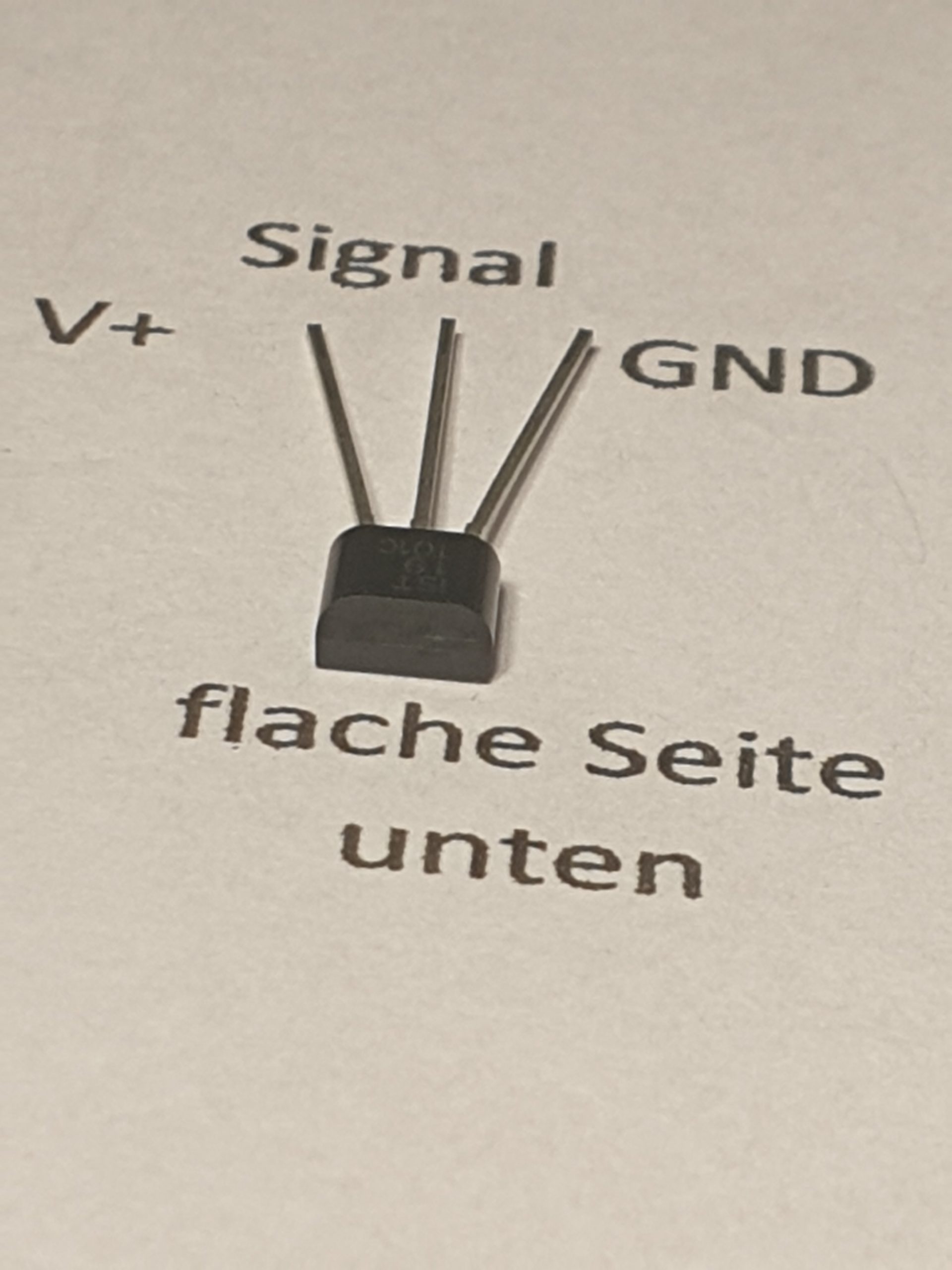
The flat side of the sensor faces down. An incorrectly wired sensor should be disposed! It seemingly measures correctly, but definitely not accurately anymore. Since the original description of the sensor is sparse, here is another description of the sensor’s pins.
TSIC sensor, flat side facing down:
Connecting the SSR
When connecting the Solid State Relay (SSR) for controlling the heating, it is important to get the polarity of SSR ports 3 and 4 correctly.
- SSR Port 3 (+) : Board
HT_RLIO02 - SSR Port 4 (-) : Board
HT_RLGND
With that, you have setup the hardware for the first time.
Tips and Tricks
Here are some collected notes about the setup of the machine:
-
Install the components in a dry spot, and as far away as possible from the boiler heatsource.
-
The SSR operates the heating capacity of around 1.000 watts, therefore assembly with a heat-conducting glue or adhesive pads doesn’t hurt.
-
If possible, the temperature sensor should not only be glued to the boiler, but rather screwed down. For Rancilio Silvia machines it is possible to reuse the metal brackets of the now-obsolete brew thermostat, for the Gaggia Classic the existing M4 screw thread of the thermostat mounting can be used.
-
For connecting the temperature sensor, do not use simple jumper cables, but instead solder them onto hook-up wires. This might be a bit fiddly to do, but the connection will be way less susceptible for loose connections, once installed permanently.
-
During the start of the ESP, after final assembly, the PID must be enabled manually on the web page in “Parameters”. Otherwise, the display will only show “PID is disabled manually”. After this, the relay should trigger and heat the boiler.