Wiring Diagrams
Contents
Warning
Working with high voltage can be deadly! Always pull the power plug of your coffee maker before touching a screw or opening the housing! Just switching the machine off is not sufficient. Smart or WiFi plugs are not necessarily providing full separation from the mains! The power plug always has to be pulled from the socket! You are working at your own risk and carry all responsibility for any modifications.
Introduction
If the previous tests were successful, let’s start with putting everything in the coffee machine’s case. Independent of the type of expansion you chose, you’ll have to supply the switching power supply and microcontroller with electricity, and fix the temperature sensor onto the boiler. This page will guide you through these steps using the example of the Rancilio Silvia. Other machines, like the Gaggia, have been modified successfully in the past as well.
Rancilio
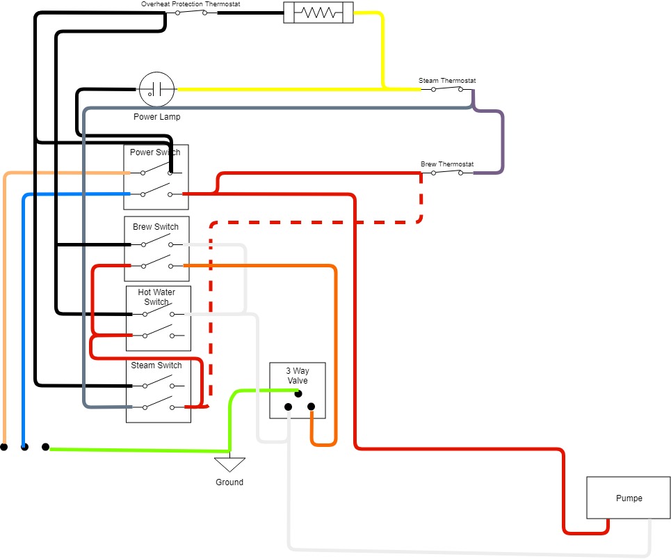
Original Wiring Diagram
The first wiring diagram shows the original configuration of the Silvia prior to any modification.
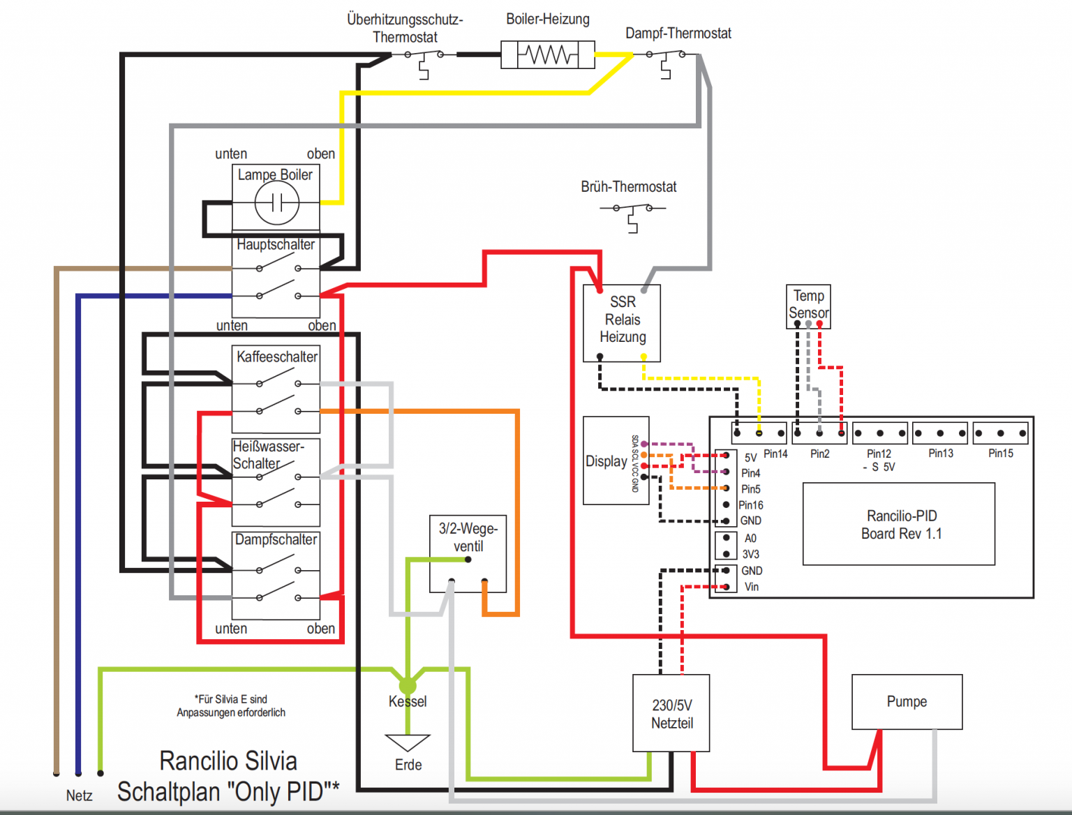
Only PID
The second wiring diagram shows the “Pid Only” modification. This version only manages the heating with the help of the temperature sensor. The pump and 3-way-valve are not controlled by the ESP microcontroller.
Only PID+
A wiring diagram for OnlyPID+, including an optocoupler for brew detection, does not yet exist. Based on the wiring diagram of the OnlyPID above, the OnlyPID+ variant adds an optocoupler parallel to the brew switch and the 3-way-valve.
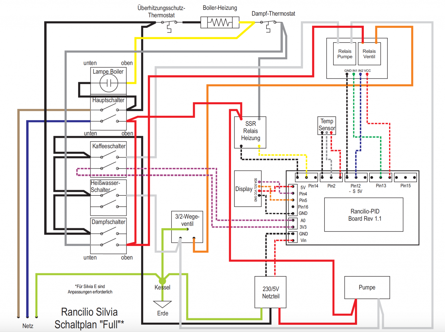
Full Expansion
The third wiring diagram shows the current “full expansion”. This version includes a temperature sensor on the boiler. Additionally, it can also control the brew time duration and do a pre-infusion (feeding some water into the portafilter, break, brew like normal). In this version, both the pump and the 3-way-valve are controlled by the ESP microcontroller.
IMPORTANT NOTE: This modification on the brew-switch can only be done if a switch without a lamp is used, or if the lamp is taken out of the lamp, or if you re-wire the lamp to use only 3.3 Volts (see LED-Mod. Otherwise, there is NO galvanic separation between 3.3 Volts and 120/230 Volts! This can possibly be a danger to you or the microcontroller!