LED-Mod of Toggle Switches
Contents
Warning
Working with high voltage can be deadly! Always pull the power plug of your coffee maker before touching a screw or opening the housing! Just switching the machine off is not sufficient. Smart or WiFi plugs are not necessarily providing full separation from the mains! The power plug always has to be pulled from the socket! You are working at your own risk and carry all responsibility for any modifications.
Introduction
In this guide, we will modify a toggle switch of the machine to run on 3.3/5 Volts instead of 230V main power. This will allow us to pass signals to the ESP microcontroller directly, without using an optocoupler (or the like).
Luckily, this is quite simple to do, without any soldering, and it is also reversible in case you want to undo the changes one day. The biggest effort for this endeavour is to remove parts of the old wiring in the machine, and to rewire the switch, but more on this at the end of this chapter.
What you will need for the modification, for each switch:
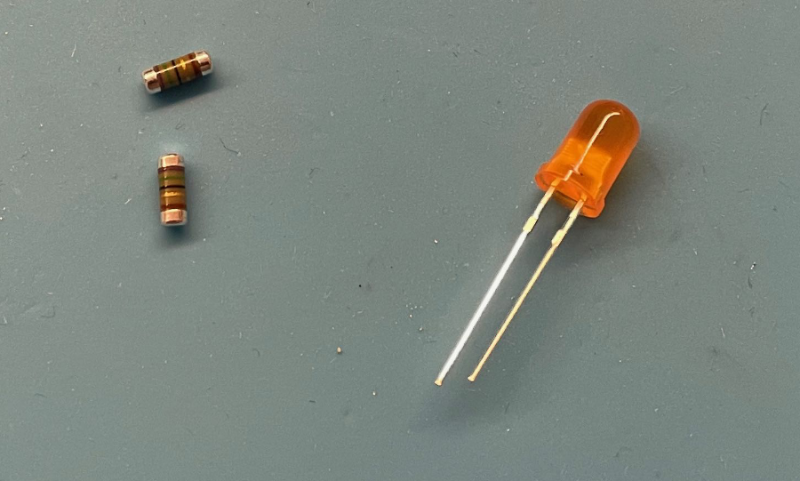
- One LED in your preferred colour, 5mm diameter
- Two resistors, type
SMD 0207 MELF
For Rancilio machines, orange/amber coloured LEDs are a decent choice, since the switch’s light-covers are already the same colour. Pick a diffusing LED with a brightness of around 1800 mcd. The resistors must match the LED and current (3.3V or 5V). Use a LED resistance calculator to get the correct values, e.g. https://www.leds-and-more.de/catalog/resistor.php.
Based on the example of an orange LED with a forward voltage of 1.8V and a current draw of 20 mA at an operating voltage of 3.3V, this will result in 75 Ω. For the LEDs which were already in use, the light was quite bright already, therefore I doubled the resistor’s values. If you are unsure about the most suitable brightness, get the LEDs and test with an assortment of different resistors. Based on the above example, you will need one LED and two MELF resistors with 75 Ω each:
The Disassembly
First, disconnect your machine from the main power. Do not just turn it off!
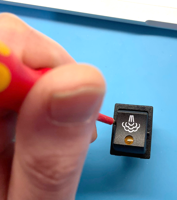
Disconnect all cables from the switches you want to modify. The switches are held in place in the machine’s case with two retainer tabs on the top- and bottom sides. Looking on the switch through the inside of the machine, gently press down on the retainers with a screwdriver until you can push the switch out of the case a bit. If you got the two retainers on top moving, repeat with a suitable tool (kitchen utilities also count as tools) with the bottom retainers. This process is a bit intricate, but the switch will come out eventually. Unmount the switches from top to bottom.
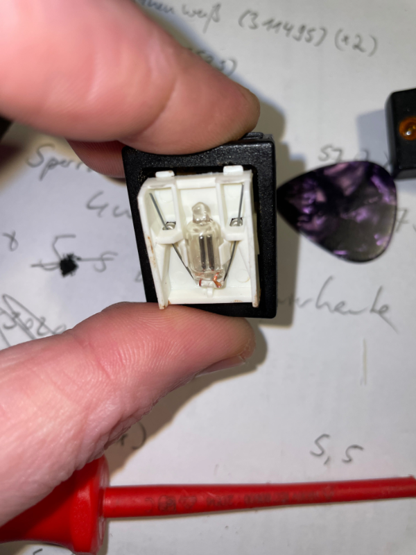
After separating the switch from the machine’s case, we can now carefully pry open the switch case, to release the cap. Use a thin screwdriver or another similar tool.
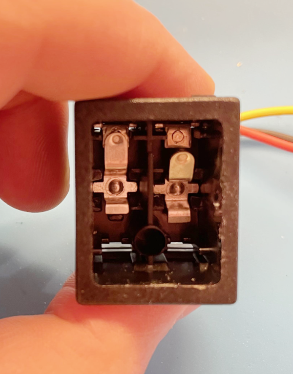
Inside the switch we will find the rocker switch itself and a 90V neon bulb. Two coil springs, two resistors and two leaf springs below the rocker. The resistors are hidden behind the two coil springs, which hold them in place. To disassemble, first pull off the coil springs, then get the resistors out. Now the neon bulb should almost fall out by itself.
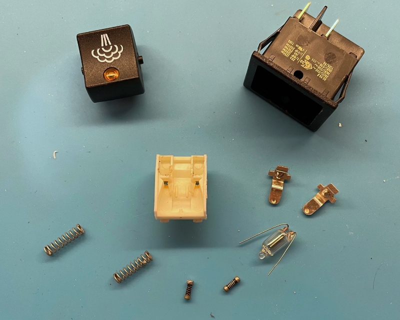
Put aside the neon bulb and resistors, in case you want to revert the mod some time later.
Reassembly
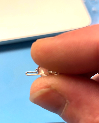
Now we can start to reassemble the switch again. Note that the LED has a flow direction. Looking at the switch from the front side, we want the anode side (+) of the LED on the right side. The positive side of the LED has a longer lead, and additionally the negative side (-) has a flattened part in the plastic case. Since the leads of the 90V bulb were a bit thicker than those of the LED in my case, and also the resistors are a bit shorter, it’s best to fold the LED leads once. This can cover up the difference in thickness.
At this point, if you want to convert your switch to a push button, you can sacrifice an old ballpoint pen for this. Just remove the coil spring from the pen and put it into the hole of the switche’s case. Depending on the spring, you might need to shorten it a bit.
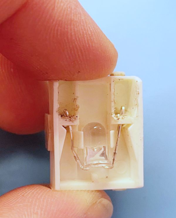
Reassemble the switch in reverse order. The switch should look like this in the end.
After modifying all the switches, we can insert them into their place in the machine again. Now the wiring can start.
Wiring
This page will include the wiring diagrams later, depending on the expansion level. For now, here’s a short textual description of the switch connections, configured as high-trigger (positive switching). On the backside of the switch, you can find numbers for the connectors, from 1-6, but only connectors 1,2,4,5 are really taken. Assuming you assembled the LED like described above, the configuration is:
- VCC on 1
- Signal on 2
- GND on 4
All switches can share VCC and GND, and the signal cables route from each switch to the according input screw terminal on the PCB base board. Since most of you, especially with an ESP, will not have enough free inputs for connecting all switches, you can for example directly connect the water switch with the input of the pump relay. In this case, the signal output (2) of the switch directly goes to the input of the relay. Currently, there is nothing to trigger on the PID with the water switch, anyways.
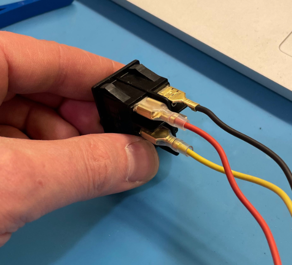
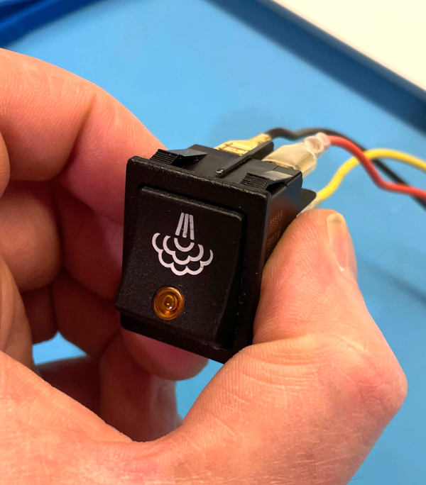
Here is a picture of the final assembly of the switch.
To Be Continued
As a next step, I will try to control the switch LEDs independent of the switch state. Since there are not enough unassigned outputs available on the base board though, I’ll continue experiments with an add-on board. If you have more questions about it, you can ask for @derchristian in the chat.
Created at 18.05.2021 by Christian (@derchristian) last change 18.05.2021 by Christian (@derchristian)