Contents
ESP32 THT PCB
We have transitioned from purely THT boards to combined SMD/THT boards.
Resistors and capacitors are now implemented as SMD components, enabling flexible partial assembly.
Here you can find information about the following revisions: 1.1
For each revision, the respective section contains information about known bugs, pin layout, features, and more.
Revision 1.1

KiCAD and Gerber files are available in our hardware repository: Minimal Rev 1.1
Bugs
Currently, there are no known bugs.
Connections on the ESP32 PCB Rev 1.6
| Header | Pin Software | Pin PCB | Connection |
|---|---|---|---|
| HT_RL | PIN 2 | OUT | SSR Heating |
| T_SENS | PIN 16 | SIG | Temperature sensor |
| I2C | PIN 21 | SDA | Display and pressure sensor - Pin SDA |
| I2C | PIN 22 | SCL | Display and pressure sensor - Pin SCL |
| V_IN | - | 5V | Switching power supply (5 Volt) |
| PV_RL | PIN 17 | Valve | Relay 3-way-valve |
| PV_RL | PIN 27 | Pump | Relay pump |
| BPSW_SW | PIN 34 | BREW | Brew switch or optocoupler |
| BPSW_SW | PIN 39 | PWR | Power switch |
| BPSW_SW | PIN 35 | STEAM | Steam switch |
| BPSW_SW | PIN 36 | WATER | Hot water switch (not yet implemented) |
| S_LED | PIN 26 | OUT | Status or Temp LED |
| W_SENS | PIN 23 | SIG | Water level sensor |
| SCALE | PIN 25 | DAT2 | Scale DAT2 |
| SCALE | PIN 32 | DAT | Scale DAT |
| SCALE | PIN 33 | CLK | Scale CLK |
| GPIO | PIN 1 | IO01 | Reserved for later use, e.g. Brew switch LED |
| GPIO | PIN 3 | IO03 | Reserved for later use, e.g. Rotary encoder CLK |
| GPIO | PIN 4 | IO04 | Reserved for later use, e.g. Rotary encoder DT |
| GPIO | PIN 5 | IO05 | Reserved for later use, e.g. Rotary encoder SW |
| GPIO | PIN 21 | SDA | Reserved for later use, e.g. IO Expander |
| GPIO | PIN 22 | SCL | Reserved for later use, e.g. IO Expander |
| GPIO | PIN 12 | IO12 | JTAG Debugger TDI |
| GPIO | PIN 13 | IO13 | JTAG Debugger TCK |
| GPIO | PIN 14 | IO14 | JTAG Debugger TMS |
| GPIO | PIN 15 | IO15 | JTAG Debugger TDO |
| GPIO | PIN 18 | IO18 | Reserved for later use, e.g. Dimmer ZC |
| GPIO | PIN 19 | IO19 | Reserved for later use, e.g. Steam switch LED |
Placement and Function
All required parts and their function are listed here:
| Inscription PCB | Part | Function |
|---|---|---|
| C1 | Electrical capacitor 220 µF | Stabilization of power supply |
| C2 | Ceramic capacitor 100 nF | Stabilization of power supply |
| R1 | Resistor 220 Ω | Resistor Status LED |
| R2 | Resistor 47 kΩ | Pull down/up steam switch |
| R3 | Resistor 47 kΩ | Pull down/up power switch |
| R4 | Resistor 4,7 kΩ | Pull up i2C |
| R5 | Resistor 4,7 kΩ | Pull up i2C |
| R6 | Resistor 47 kΩ | Pull down/up brew switch or optocoupler |
| R7 | Resistor 47 kΩ | Pull down/up hot water switch |
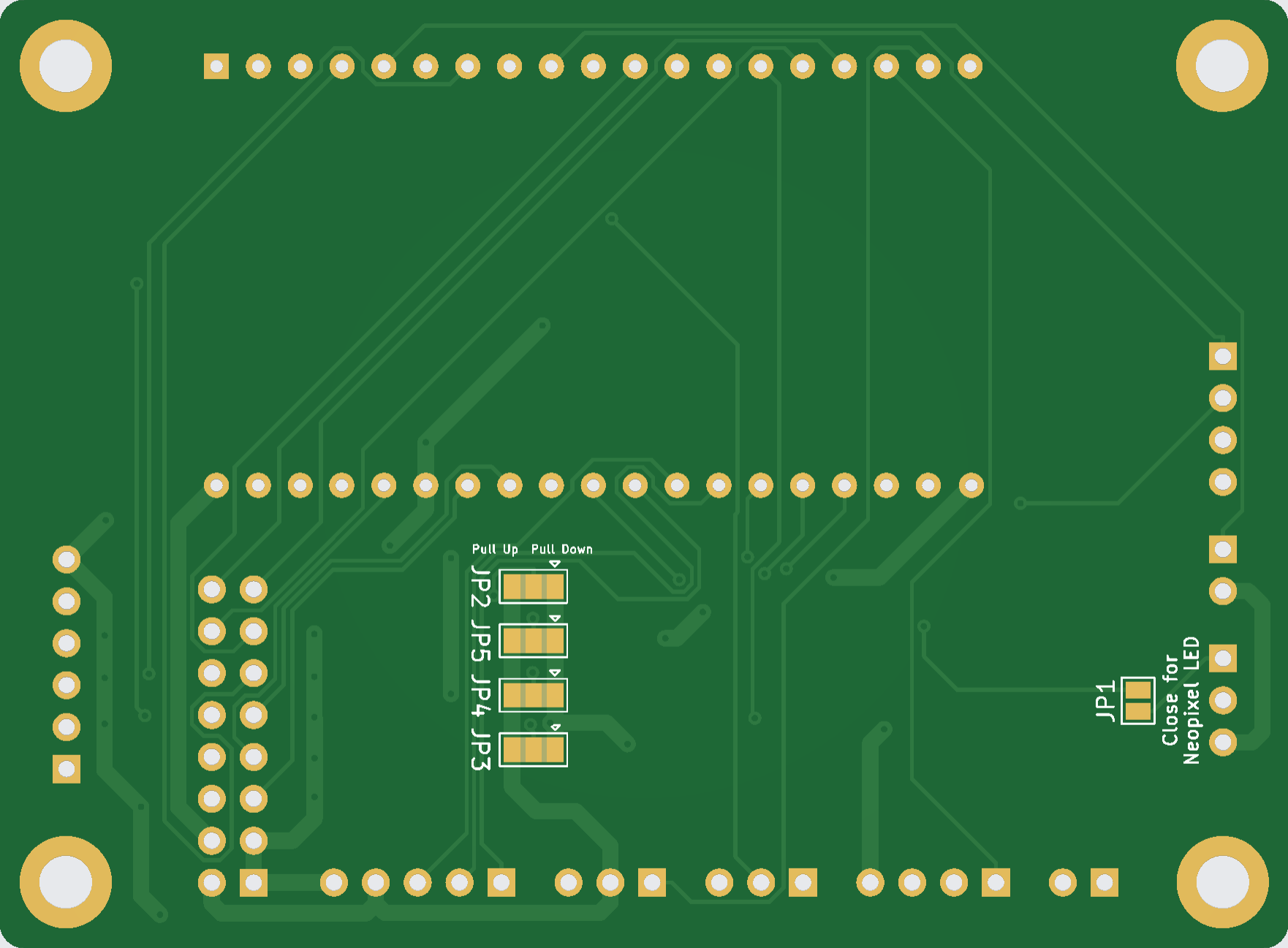
| JP1 | Solder jumper | Resistor bypass for LED when using WS1812 LED |
| JP2 | Solder jumper | Pull down or Pull up for hot water switch |
| JP3 | Solder jumper | Pull down or Pull up for brew switch or optocoupler |
| JP4 | Solder jumper | Pull down or Pull up for power switch |
| JP5 | Solder jumper | Pull down or Pull up for steam switch |
Jumper Settings
The solder jumpers allow switching the resistors for the hot water, brew, power, and steam switches between pull-down and pull-up. The resistors define the state of the switch input when the switch is not actuated. The default configuration is that all jumpers are soldered to pull-down. When using an optocoupler for brew detection, in most cases solder jumper JP3 must be configured as pull-up.
Changes to THT Rev 1.6
- Resistors and capacitors implemented as SMD components
- Pull resistors for brew, hot water, steam, and power implemented via solder jumpers