Software Teil II
Contents
Introduction
In this chapter we will explain how to get the program code onto your NodeMCU. You can start with that as soon as you have you microcontroller at hand, no other parts are needed. For later testing, you will however need at least the temperature sensor
Open the program in Arduino IDE
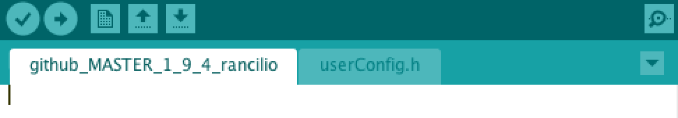
In the current release there are (among others) two files:
- rancilio-pid.ino
- userConfig.h
rancilio-pid.ino contains the actual program while userConfig.h holds all user specific configuration options.
When you open the .ino file, the other files which belond to the project are automatically opend in separate tabs within Arduino IDE and can be edited and saved directly from here.
Preferences
The most important functions have to be parameterized in userConfig.h. Please remember to set the correct PID mode, temperature sensor and possibly display.
// Display -> siehe ./customization/Displey.md
#define DISPLAY 2            // 2 = Defaulf AZDelivery Display
#define DISPLAYTEMPLATE 1    // 1: Standard Display Template, 2: Minimal Template
#define MACHINELOGO 1        // 1 = Rancilio, 2 = Gaggia
#define DISPALYROTATE U8G2_R0   // rotate display clockwise: U8G2_R0 = no rotation; U8G2_R1 = 90°; U8G2_R2 = 180°; U8G2_R3 = 270°
#define SHOTTIMER  1 // 0: no SHOTTIMER, 1: SHOTTIMER

// Wlan and Connection
#define OFFLINEMODUS 0       // 0 = Blynk and WIFI are used; 1 = offline mode (only preconfigured values in code are used!)
#define FALLBACK 1           // 1 = fallback to values stored in eeprom, if blynk is not working; 0 = deactivated
#define OTA true             // true = activate update via OTA
#define MQTT 0               // 1 = MQTT enabled, 0 = MQTT disabled
#define GRAFANA 1            // 1 = grafana visualisation. Access required, 0 = off (default)
#define MAXWIFIRECONNECTS 5  // maximum number of reconnects; use -1 to set to maximum ("deactivated")
#define WIFICINNECTIONDELAY 10000 // delay between reconnects in ms

// PID & Hardware
#define ONLYPID 1            // 1 = Only PID, no preinfusion; 0 = PID and preinfusion
#define BREWDETECTION 1      // 0 = off; 1 = Software; 2 = Hardware
#define COLDSTART_PID 1     // 1 = default COLDStart Values , 2 = eigene Werte via Blynk, Expertenmodusaktiv
#define TRIGGERTYPE HIGH     // LOW = low trigger, HIGH = high trigger relay

//E-Trigger
#define ETRIGGER 0  // 0: no Trigger (for Raniclio without E) 1: Trigger for CPU of Rancilio E
#define ETRIGGERTIME 60 // Seconds, time between for Trigger Signal
#define PINETRIGGER 16 // Pin for Etrigger Relay
#define TRIGGERRELAYTYPE HIGH  // LOW = low trigger, HIGH = high trigger relay for ETrigger

// Wifi -> Infos siehe unten
#define HOSTNAME "Rancilio"
#define D_SSID "myssid"
#define PASS "mypass"

// OTA -> siehe unten
#define OTAHOST "Rancilio"   // Name to be shown in ARUDINO IDE Port
#define OTAPASS "otapass"    // Password for OTA updtates

//MQTT
#define MQTT_USERNAME "myuser"
#define MQTT_PASSWORD "mypass"
#define MQTT_TOPIC_PREFIX "custom/Küche."  // topic will be "<MQTT_TOPIC_PREFIX><HOSTNAME>/<READING>"
#define MQTT_SERVER_IP "XXX.XXX.XXX.XXX"       // IP-Address of locally installed mqtt server
#define MQTT_SERVER_PORT 1883

// BLynk
#define AUTH "myauth"
#define BLYNKADDRESS "blynk.clevercoffee.de"         // IP-Address of used blynk server
#define BLYNKPORT 8080  //Port for blynk server


//PID - offline values
#define SETPOINT 95  // Temperatur setpoint
#define AGGKP 69     // Kp Normal
#define AGGTN 399    // Tn
#define AGGTV 0      // Tv

// PID Coldtart
#define STARTKP 50   // Start Kp during coldstart
#define STARTTN 150  // Start Tn during cold start


//PID - values for offline brewdetection
#define AGGBKP 50    // Kp
#define AGGBTN 0   // Tn
#define AGGBTV 20    // Tv

//backflush values
#define FILLTIME 3000       // time in ms the pump is running
#define FLUSHTIME 6000      // time in ms the 3-way valve is open -> backflush
#define MAXFLUSHCYCLES 5      // number of cycles the backflush should run; 0 = disabled

//PIN BELEGUNG
#define ONE_WIRE_BUS 2  // TEMP SENSOR PIN

#define pinRelayVentil    12    //Output pin for 3-way-valve
#define pinRelayPumpe     13    //Output pin for pump
#define pinRelayHeater    14    //Output pin for heater

//#define OLED_RESET 16     //Output pin for dispaly reset pin
#define OLED_SCL 5        //Output pin for dispaly clock pin
#define OLED_SDA 4        //Output pin for dispaly data pin
#define SCREEN_WIDTH 128 // OLED display width, in pixels
#define SCREEN_HEIGHT 64 // OLED display height, in pixels

// Historic, no settings
#define PONE 1               // 1 = P_ON_E (default), 0 = P_ON_M (special PID mode, other PID-parameter are needed)
#define TEMPSENSOR 2         // 2 = TSIC306
Wifi
Under Wifi please specify the desired hostname of the NodeMCU, the SSID to connect to and the according Wifi password. Please also check that your SSID doesn’t contain any blank spaces or special characters as those often lead to problems.
#define HOSTNAME "Rancilio"

#define D_SSID "wifiname"

#define PASS "wifipass"
Blynk
Under Blynk, enter your Auth token from Part 1 as AUTH.
#define AUTH "myauth"
#define BLYNKADDRESS "blynk.clevercoffee.de"         // IP-Address of used blynk server
#define BLYNKPORT 8080  //Port for blynk server
PID
Here you can define your initial PID values or just start with the “factory defaults”
OTA
Here, Over The Air update is set up. This is important once your NodeMCU is buried deep in your machine and you want to update to a new software version.
Flashing the code
Make sure the Auth token as well as the Wifi data you have entered is correct.
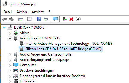
Also make sure you have chosen the right COM port for flashing. If you are unsure, you can check the COM port number in device manager
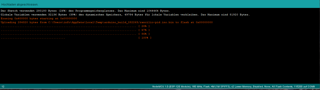
Next, click on the arrow symbol to start the upload to the Microcontroller
Testing
If everything has worked fine, you can see the communication between your NodeMCU and Blynk in the Serial Monitor
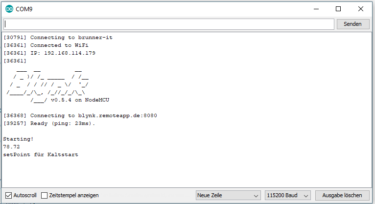
If that has worked and if you already have a temperature sensor connected, you can see you current room temperature in the Blynk app. Now you can start adding more and more parts to you setup, like the SSR or a display and continue testing.
perform OTA update (optional)
In order to do an OTA update, the machine has to be turned on and has to be in the same network as your PC running Arduino IDE. You will now see your NodeMCU under Tools > Port > Network > “Hostname