Contents
- ESP32 PCB
ESP32 PCB
Several different revisions of our PCB are in use by now.
Here you can find information about the following revisions: 1.2, 1.3, 1.5. and 1.6
For each revision, the respective section contains information about known bugs, pin layout, features, and more.
Revision 1.6
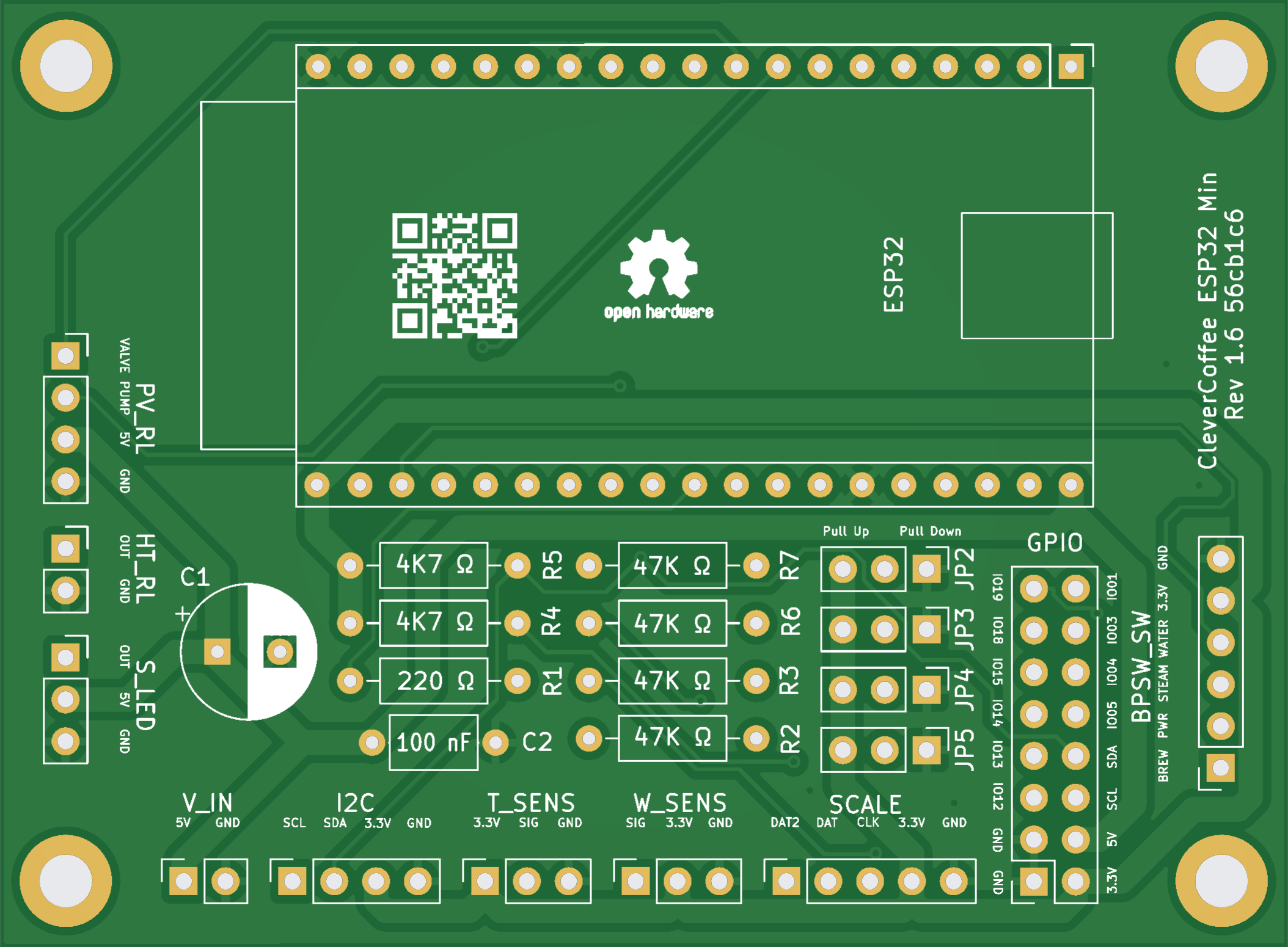
KiCAD and Gerber files are available in our hardware repository: Minimal Rev 1.6
Bugs
Currently, there are no known bugs.
Connections on the ESP32 PCB Rev 1.6
| Header | Pin Software | Pin PCB | Connection |
|---|---|---|---|
| HT_RL | PIN 2 | OUT | SSR Heating |
| T_SENS | PIN 16 | SIG | Temperature sensor |
| I2C | PIN 21 | SDA | Display and pressure sensor - Pin SDA |
| I2C | PIN 22 | SCL | Display and pressure sensor - Pin SCL |
| V_IN | - | 5V | Switching power supply (5 Volt) |
| PV_RL | PIN 17 | Valve | Relay 3-way-valve |
| PV_RL | PIN 27 | Pump | Relay pump |
| BPSW_SW | PIN 34 | BREW | Brew switch or optocoupler |
| BPSW_SW | PIN 39 | PWR | Power switch |
| BPSW_SW | PIN 35 | STEAM | Steam switch |
| BPSW_SW | PIN 36 | WATER | Hot water switch (not yet implemented) |
| S_LED | PIN 26 | OUT | Status or Temp LED |
| W_SENS | PIN 23 | SIG | Water level sensor |
| SCALE | PIN 25 | DAT2 | Scale DAT2 |
| SCALE | PIN 32 | DAT | Scale DAT |
| SCALE | PIN 33 | CLK | Scale CLK |
| GPIO | PIN 1 | IO01 | Reserved for later use, e.g. Brew switch LED |
| GPIO | PIN 3 | IO03 | Reserved for later use, e.g. Rotary encoder CLK |
| GPIO | PIN 4 | IO04 | Reserved for later use, e.g. Rotary encoder DT |
| GPIO | PIN 5 | IO05 | Reserved for later use, e.g. Rotary encoder SW |
| GPIO | PIN 21 | SDA | Reserved for later use, e.g. IO Expander |
| GPIO | PIN 22 | SCL | Reserved for later use, e.g. IO Expander |
| GPIO | PIN 12 | IO12 | JTAG Debugger TDI |
| GPIO | PIN 13 | IO13 | JTAG Debugger TCK |
| GPIO | PIN 14 | IO14 | JTAG Debugger TMS |
| GPIO | PIN 15 | IO15 | JTAG Debugger TDO |
| GPIO | PIN 18 | IO18 | Reserved for later use, e.g. Dimmer ZC |
| GPIO | PIN 19 | IO19 | Reserved for later use, e.g. Steam switch LED |
Placement and Function
All required parts and their function are listed here:
| Inscription PCB | Part | Function |
|---|---|---|
| C1 | Electrical capacitor 220 µF | Stabilization of power supply |
| C2 | Ceramic capacitor 100 nF | Stabilization of power supply |
| R1 | Resistor 220 Ω | Resistor Status LED |
| R2 | Resistor 47 kΩ | Pull down/up steam switch |
| R3 | Resistor 47 kΩ | Pull down/up power switch |
| R4 | Resistor 4,7 kΩ | Pull up i2C |
| R5 | Resistor 4,7 kΩ | Pull up i2C |
| R6 | Resistor 47 kΩ | Pull down/up brew switch or optocoupler |
| R7 | Resistor 47 kΩ | Pull down/up hot water switch |
| JP1 | Solder jumper | Resistor bypass for LED when using WS1812 LED |
| JP2 | Jumper | Pull down or Pull up for hot water switch |
| JP3 | Jumper | Pull down or Pull up for brew switch or optocoupler |
| JP4 | Jumper | Pull down or Pull up for power switch |
| JP5 | Jumper | Pull down or Pull up for steam switch |
Jumper Settings
The jumpers allow switching the resistors between pulldown and pullup for the hot water, brewing, power, and steam switches. These resistors define the state of the switch input when it is not activated. The standard configuration has all jumpers set to pulldown.
Changes
- Rounded corners for the PCB
- Pull resistors for brewing, hot water, steam, and power are pluggable
- Adjusted position and size of the installation space for Elko and Kerko
Revision 1.5
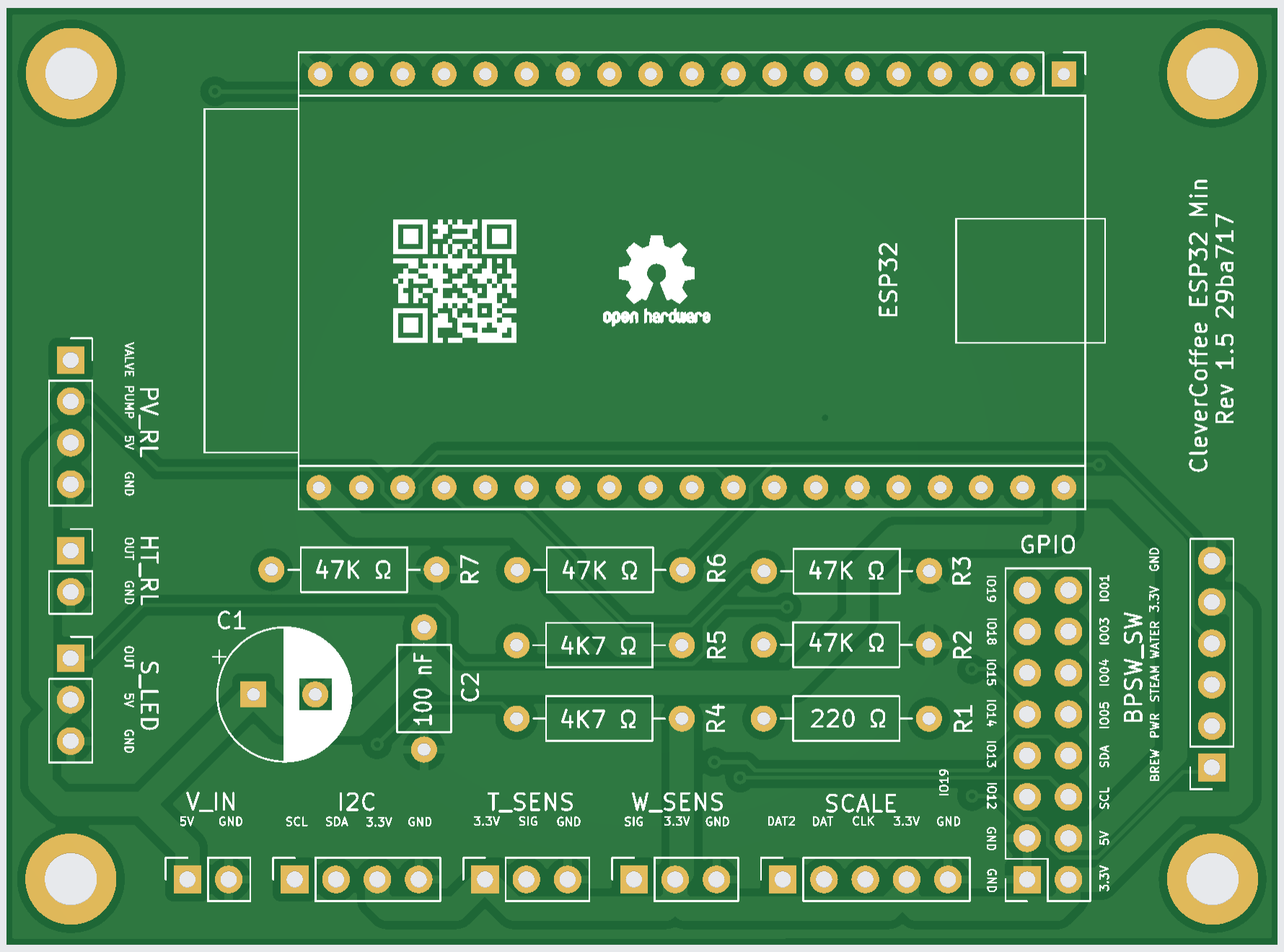
KiCAD and Gerber files are available in our hardware repository: Minimal Rev 1.5
Bugs
Currently, there are no known bugs.
Connections on the ESP32 PCB Rev 1.5
| Header | Pin Software | Pin PCB | Connection |
|---|---|---|---|
| HT_RL | PIN 2 | OUT | SSR Heating |
| T_SENS | PIN 16 | SIG | Temperature sensor |
| I2C | PIN 21 | SDA | Display and pressure sensor - Pin SDA |
| I2C | PIN 22 | SCL | Display and pressure sensor - Pin SCL |
| V_IN | - | 5V | Switching power supply (5 Volt) |
| PV_RL | PIN 17 | Valve | Relay 3-way-valve |
| PV_RL | PIN 27 | Pump | Relay pump |
| BPSW_SW | PIN 34 | BREW | Brew switch or optocoupler |
| BPSW_SW | PIN 39 | PWR | Power switch |
| BPSW_SW | PIN 35 | STEAM | Steam switch |
| BPSW_SW | PIN 36 | WATER | Hot water switch (not yet implemented) |
| S_LED | PIN 26 | OUT | Status LED |
| W_SENS | PIN 23 | SIG | Water level sensor |
| SCALE | PIN 25 | DAT2 | Scale DAT2 |
| SCALE | PIN 32 | DAT | Scale DAT |
| SCALE | PIN 33 | CLK | Scale CLK |
| GPIO | PIN 1 | IO01 | Reserved for later use, e.g. Brew switch LED |
| GPIO | PIN 3 | IO03 | Reserved for later use, e.g. Rotary encoder CLK |
| GPIO | PIN 4 | IO04 | Reserved for later use, e.g. Rotary encoder DT |
| GPIO | PIN 5 | IO05 | Reserved for later use, e.g. Rotary encoder SW |
| GPIO | PIN 21 | SDA | Reserved for later use, e.g. IO Expander |
| GPIO | PIN 22 | SCL | Reserved for later use, e.g. IO Expander |
| GPIO | PIN 12 | IO12 | JTAG Debugger TDI |
| GPIO | PIN 13 | IO13 | JTAG Debugger TCK |
| GPIO | PIN 14 | IO14 | JTAG Debugger TMS |
| GPIO | PIN 15 | IO15 | JTAG Debugger TDO |
| GPIO | PIN 18 | IO18 | Reserved for later use, e.g. Dimmer ZC |
| GPIO | PIN 19 | IO19 | Reserved for later use, e.g. Steam switch LED |
Placement and Function
All required parts and their function are listed here:
| Inscription PCB | Part | Function |
|---|---|---|
| C1 | Electrical capacitor 220 µF | Stabilization of power supply |
| C2 | Ceramic capacitor 100 nF | Stabilization of power supply |
| R1 | Resistor 220 Ω | Resistor Status LED |
| R2 | Resistor 47 kΩ | Pull down steam switch |
| R3 | Resistor 47 kΩ | Pull down power switch |
| R4 | Resistor 4,7 kΩ | Pull up i2C |
| R5 | Resistor 4,7 kΩ | Pull up i2C |
| R6 | Resistor 47 kΩ | Pull down/up brew switch or optocoupler |
| R7 | Resistor 47 kΩ | Pull down hot water switch |
| JP1 | Solder jumper | Resistor bypass for LED when using WS1812 LED |
| JP2 | Solder jumper | Pull down or Pull up for brew switch or optocoupler |
Revision 1.3
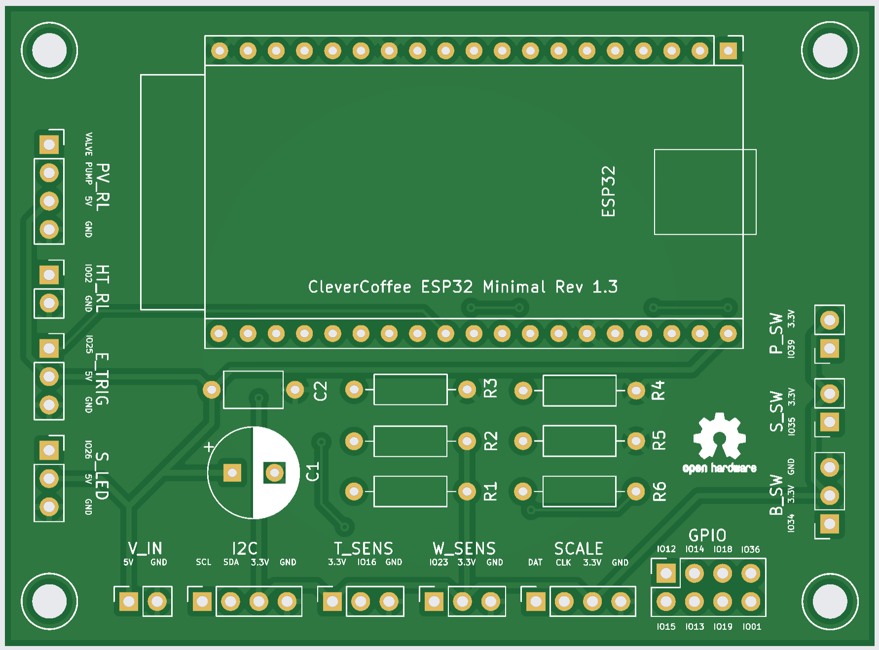
KiCAD and Gerber files are available in our hardware repository: Minimal Rev 1.3
Bugs
Faulty optocoupler for brew detection:
- Only compatible with high level trigger optocoupler
- Workaround for low level trigger: Don’t solder pulldown resistor
R3, and depending on software version, set the following:- MASTER ->
OPTOCOUPLER_TYPEtoLOW - 3.3.0 and older ->
PINMODEVOLTAGESENSORtoINPUT_PULLUPandVOLTAGESENSORtoLOW
- MASTER ->
- Missing GPIO: IO03, IO04, IO05
Connections on the ESP32 PCB Rev 1.3
| Header | Pin Software | Pin PCB | Connection |
|---|---|---|---|
| HT_RL | PIN 2 | IO02 | SSR Heating |
| T_SENS | PIN 16 | IO16 | Temperature sensor |
| I2C | PIN 21 | SDA | Display and pressure sensor - PIN SDA |
| I2C | PIN 22 | SDL | Display and pressure sensor - PIN SCL |
| V_IN | - | V_IN | Switching power supply (5 Volt) |
| PV_RL | PIN 17 | Valve | Relay 3-way-valve |
| PV_RL | PIN 27 | Pump | Relay pump |
| B_SW | PIN 34 | IO34 | Brew switch or optocoupler |
| S_SW | PIN 35 | IO35 | Steam switch |
| P_SW | PIN 39 | IO39 | Power switch |
| E_TRIG | PIN 25 | IO25 | Trigger Silvia E CPU Up to s/w version 3.X, afterwards SCALE DAT2 |
| S_LED | PIN 26 | IO26 | Status LED |
| W_SENS | PIN 23 | IO23 | Water level sensor |
| SCALE | PIN 32 | DAT | Scale DAT |
| SCALE | PIN 33 | CLK | Scale CLK |
| GPIO | PIN 1 | IO01 | Reserved for later use, e.g. Brew switch LED |
| GPIO | PIN 12 | IO12 | JTAG Debugger TDI |
| GPIO | PIN 13 | IO13 | JTAG Debugger TCK |
| GPIO | PIN 14 | IO14 | JTAG Debugger TMS |
| GPIO | PIN 15 | IO15 | JTAG Debugger TDO |
| GPIO | PIN 18 | IO18 | Reserved for later use, e.g. Dimmer ZC |
| GPIO | PIN 19 | IO19 | Reserved for later use, e.g. Steam switch LED |
| GPIO | PIN 36 | IO36 | Hot water switch (not yet implemented) |
Placement and Function
All required parts and their function are listed here:
| Inscription PCB | Part | Function |
|---|---|---|
| C1 | Electrical capacitor 220 µF | Stabilization of power supply |
| C2 | Ceramic capacitor 100 nF | Stabilization of power supply |
| R1 | Resistor 4,7 kΩ | Pull up i2C |
| R2 | Resistor 4,7 kΩ | Pull up i2C |
| R3 | Resistor 47 kΩ | Pull down brew switch |
| R4 | Resistor 47 kΩ | Pull down power switch |
| R5 | Resistor 47 kΩ | Pull down steam switch |
| R6 | Resistor 220 Ω | Resistor Status LED |
| JP1 | Solder jumper | Resistor bypass for LED when using WS1812 LED |
Revision 1.2
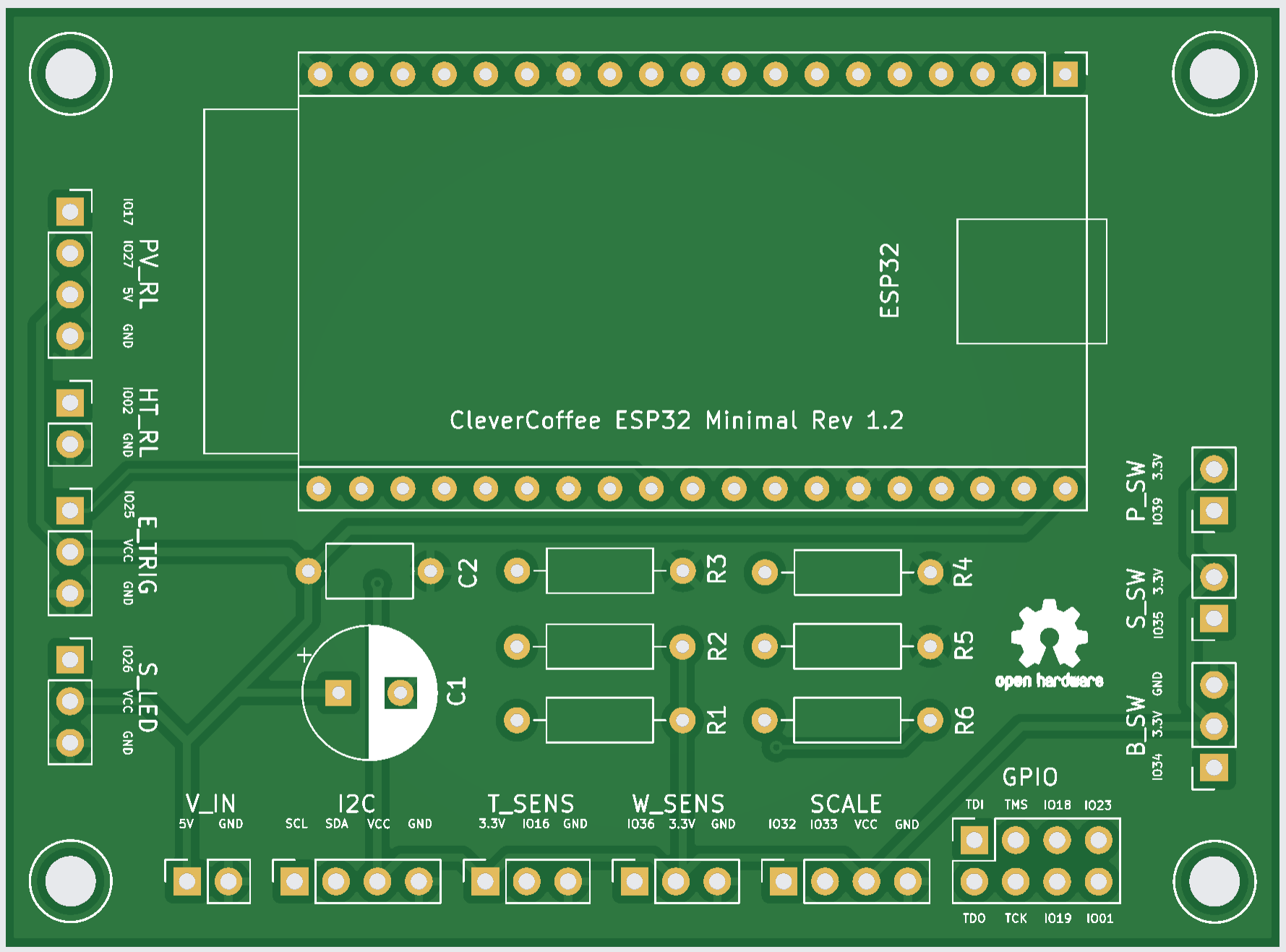
KiCAD and Gerber files are available in our hardware repository: Minimal Rev 1.2
Bugs
Errors in PCB inscription: HEADER | PCB Inscription | Correct Inscription
-
S_LED VCC 5V E_TRIG VCC 5V W_SENS IO36 IO23 GPIO IO23 IO36
Faulty optocoupler for brew detection:
- Only compatible with high level trigger optocoupler
- Workaround for low level trigger: Don’t solder pulldown resistor
R3, and depending on software version, set the following:- MASTER ->
OPTOCOUPLER_TYPEtoLOW - 3.3.0 and older ->
PINMODEVOLTAGESENSORtoINPUT_PULLUPandVOLTAGESENSORtoLOW
- MASTER ->
- Missing GPIO: IO03, IO04, IO05
Connectors of the ESP32 PCB Rev 1.2
| Header | PIN Software | PIN PCB | Connection |
|---|---|---|---|
| HT_RL | PIN 2 | IO02 | SSR Heating |
| T_SENS | PIN 16 | IO16 | Temperature sensor |
| I2C | PIN 21 | SDA | Display and pressure sensor - PIN SDA |
| I2C | PIN 22 | SDL | Display and pressure sensor - PIN SCL |
| V_IN | - | V_IN | Switching power supply (5 Volt) |
| PV_RL | PIN 17 | Valve | Relay 3-way-valve |
| PV_RL | PIN 27 | Pump | Relay pump |
| B_SW | PIN 34 | IO34 | Brew switch or optocoupler |
| S_SW | PIN 35 | IO35 | Steam switch |
| P_SW | PIN 39 | IO39 | Power switch |
| E_TRIG | PIN 25 | IO25 | Trigger Silvia E CPU Up to s/w version 3.X, afterwards SCALE DAT2 |
| S_LED | PIN 26 | IO26 | Status LED |
| W_SENS | PIN 23 | IO23 | Water level sensor |
| SCALE | PIN 32 | DAT | Scale DAT |
| SCALE | PIN 33 | CLK | Scale CLK |
| GPIO | PIN 1 | IO01 | Reserved for later use, e.g. Brew switch LED |
| GPIO | PIN 12 | IO12 | JTAG Debugger TDI |
| GPIO | PIN 13 | IO13 | JTAG Debugger TCK |
| GPIO | PIN 14 | IO14 | JTAG Debugger TMS |
| GPIO | PIN 15 | IO15 | JTAG Debugger TDO |
| GPIO | PIN 18 | IO18 | Reserved for later use, e.g. Dimmer ZC |
| GPIO | PIN 19 | IO19 | Reserved for later use, e.g. Steam switch LED |
| GPIO | PIN 36 | IO36 | Hot water switch (not yet implemented) |
Placement and Function
All required parts and their function are listed here:
| Inscription PCB | Part | Function |
|---|---|---|
| C1 | Electrical capacitor 220 µF | Stabilization of power supply |
| C2 | Ceramic capacitor 100 nF | Stabilization of power supply |
| R1 | Resistor 4,7 kΩ | Pull up i2C |
| R2 | Resistor 4,7 kΩ | Pull up i2C |
| R3 | Resistor 47 kΩ | Pull down brew switch |
| R4 | Resistor 47 kΩ | Pull down power switch |
| R5 | Resistor 47 kΩ | Pull down steam switch |
| R6 | Resistor 220 Ω | Resistor Status LED |
| JP1 | Solder jumper | Resistor bypass for LED when using WS1812 LED |