Installation
Contents
As a first step, we suggest to cut all cables to a length of around 60 cm. After connecting them on one end, you can route them through the machine and finally cut them to length as required.
Preparations:
- Flash the ESP microcontroller (make sure the WiFi works)
- Solder the PCB base board
- Optional: 3D-print or order a display case
Time required:
- PID Only: around 3 hours
- Full Expansion: additional 2-3 hours
Disassembly
First, we’ll have to disassemble the machine. Here you can find a link to a tutorial (german).
PID Only
Switch thermostat with new temperature sensor
Solder cables (0.14mm²) to the temperature sensor and isolate the joints with some heat shrink tube. Take care to notice the correct pin assignment! See “Connecting the Temperature Sensor” chapter. We recommend to use the following color coding:
- Red:
+(VCC) - Black:
-(GND) - Green:
Signal
Mark the loose ends of the cables.
Now pull the thermostat connectors red cable and grey cable.
Loosen screws 1 and 2, loosen screw 3 a bit.
Set aside the old thermostat and clean the area of leftover heat paste.
Prepare the bracket with a long enough screw, washers and nuts in a way that the screw will press down the new temperature sensor onto the boiler once you tighten the screws of the original bracket.
Now put a small amount of fresh heat paste on the flat side of the temperature sensor, place it under the new screw and tighten the bracket. The temperature sensor should sit firmly on the boiler without getting damaged by the force pushing it down.
Power Supply
Use a blue 1.5mm² cable and put on one of the piggy back disconnects which have an additional, angled connector (we will refer to this as “Piggy back connector with junction”). Connect it with the original red cable.
Use another blue 1.5mm² cable and put on a piggy back disconnect. Wrap everything with heat shrink tube and connect it. One of the cables goes to the SSR relay for heating, the other one goes to the power supply. Which one goes where does not matter.
Use a black 1.5mm² cable and put on a piggy back disconnect with junction. Pull off the lower connector of the thermo-safety sensor, connect it to the new angled connector, and reconnect both to the original connector.
Route the cables as you like it, preferrably away from the heat sources. Think of a good place for the power supply, then cut the cables accordingly.
If you’re using the 5V power supply listed in the Bill of Materials, connect the neutral input N (blue) with blue and the line input L (black) with brown. The output of the power supply (black and red) connects to the V_IN 5V input on the PCB base board.
SSR Heating Relay
Choose a mounting place for the SSR. For example inside the Rancilio Silvia E it can be connected with double-sided tape above the “CPU”, next to the water tube. Alternatively, there is a screw sticking out on the front side of the machine (below the front cover), which can be used to attach the SSR with a screw-nut.
Prepare one of the blue cables from the step above, and put a ring connector for M5 on it (after shortening the cable accordingly). Screw it onto one of the output connectors of the SSR. Use another 1.5mm² cable, put on a ring connector for M5 and connect it to the other output connector of the SSR. Route the cable to the connector with the grey cable, which originally was connected to the thermostat. Shorten it to length and put on another piggy back disconnect and heat shrink tube.
Connect two cables (red and black) to the input-side of the SSR. I used 0.5mm² cables and also put on ring connectors for M3. You can instead also use 0.14mm² cables with wire terminations.
Mark the loose cable ends and route them to the 3-way-valve.
Installation of the Controller
The ESP microcontroller should be mounted onto the PCB base board. It comes with adhesive PCB holders which you can use to put it to any place you prefer, where all the cables will lead to.
Full Expansion
Important! When connecting the brew switch, please note the warning about galvanic isolation between 230V and 3.3/5V inside the switch! (If you follow the guide below, you don’t have to take “additional” care).
The following steps were done with a Rancilio Silvia V2. Installations on other models might differ.
In the full expansion build, the ESP microcontroller operates the brewing (including the 3-way-valve) as well as the steam mode. For this to work, there are roughly three different steps to take, which will be described in details below.
- Modify the switch to use LEDs
- Connecting the pump
- Connecting the 3-way-valve
Modify The Switch
You will have to modify the brew switch and steam switch to use LEDs. Follow this guide: LED-Mod.
Since both switches will be modified, it is suitable to route one pair of cables with 3.3V and GND for both switches, and route it from one switch to the other. This way, you will need only four instead of six cables going across the machine (including the signal lines).
Connecting The 3-Way-Valve
On our relay board, we will be using SW1 for controlling the 3-way-valve.
- From the main switch on
Lside (line, black), connect a cable to the pump- and 3-way-valve relay. This cable will be shared by the pump and the 3-way-valve. Terminate the cable on the relay-side with a 3-way screw joint or another piggy back disconnect with junction. - Another (short) cable going from the piggy back to
SW1on the 230V-side of the relay. - On the other side of
SW1switch of the relay, connect a cable, shorten it to the correct length going to the 3-way-valve. Use a piggy back, then disconnect the orange cable from the 3-way-valve and connect the new cable instead. - Route an additional cable
N(neutral, red) from the 3-way-valve to the switch, and connect it where the white cable was. - Route cables for 5V, GND and 3-way-valve signal to the relay. In case you are using Dupont connectors, it is best to already include a forth lane for the pump signal. At the relay, make sure that the signal wire is connected correctly (if the 3-way-valve is connected to
SW1like above, then connect signal for 3-way-valve toCH1). - Configure software, flash it to the ESP, connect machine to main power and test the brew switch. The 3-way-valve should trigger audibly when the brew switch is pressed.
- Before continuing, disconnect the machine from main power.
Connecting The Pump
On our relay board, we will be using SW2 for controlling the pump.
- Connect a second (short) cable to the 3-way screw joint of the previous step 1 “Connecting The 3-Way-Valve” to
SW2on the 230V-side of the relay. - Connect a cable to the outgoing connector of
SW2on the relay. Route the cable to the pump, shorten it accordingly and terminate it with another piggy back with junction. Pull the white cable from the pump, connect it to the new piggy back, and connect both to the pump again. - Connect the signal cable between PCB output
PV_RLPUMPand the relay,CH2. - Connect the machine to main power again and test the brew switch.
- If everything works: Congratulations, you completed your full expansion successfully!
- If the pump does not work: Probably your relay only triggers for a zero-crossing (more info here: Bill Of Materials). To test this, connect a 100 kΩ resistor (1 watt rating, see further information in the bill of materials) parallel to the pump. For this, I disconnected both cables from the pump and cut the connectors, Then I put on new connectors, and added one leg of the resistor to each of the connectors. Now the two connectors must be put on and off the pump together carefully, as they are connected through the resistor now. Finally, do another round of brew tests and enjoy your full expansion build!
Display
There are countless possibilities on how to position the display. Below, you can see two variations:
| 3D-printed display case | Powered by Dremel |
|---|---|
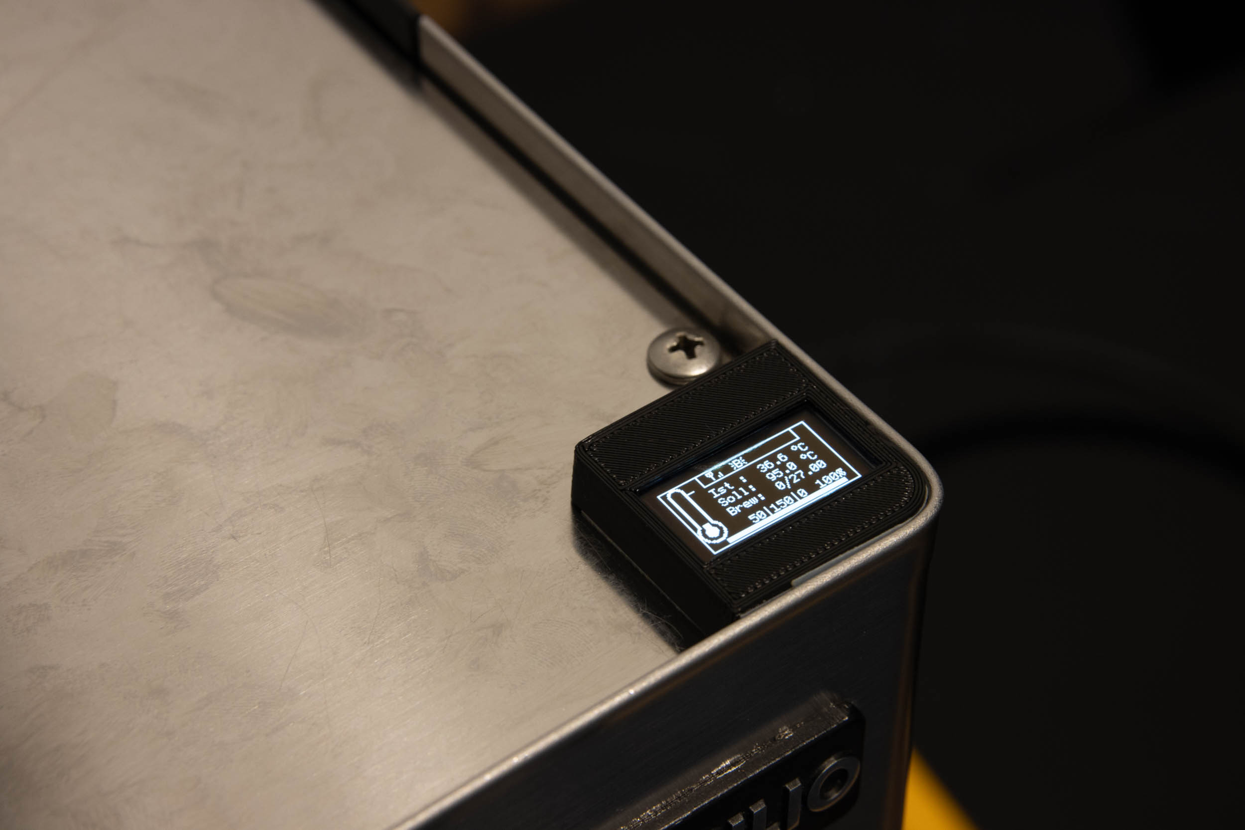 | 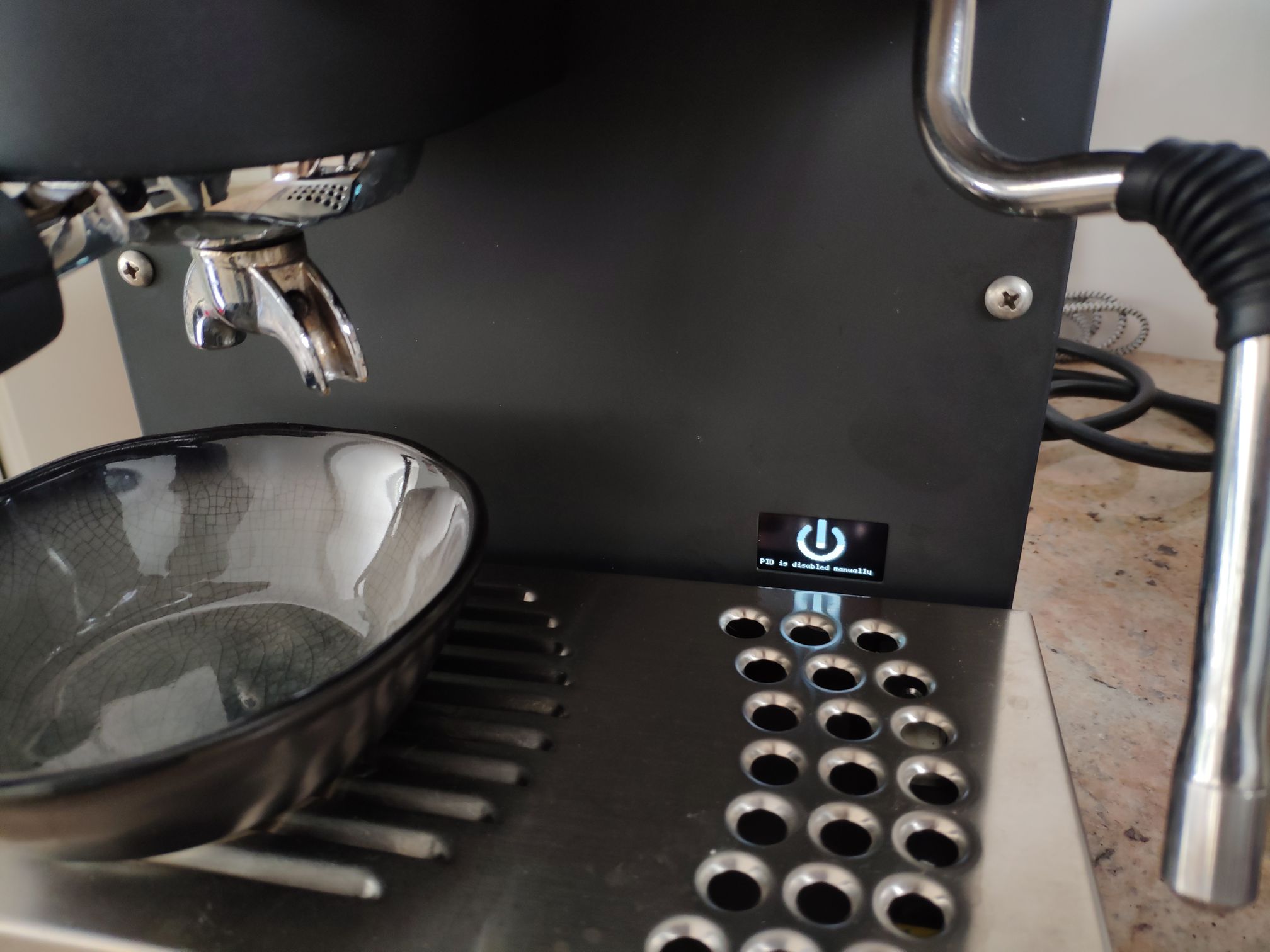 |
If you own a rotary power tool, bring some skill with it and are not stopped by the fact that you will do irreversible change to your machine, you can craft a fine and presentable solution with it.
If you are looking for a reversible solution, you should use a 3D-printed case. There is no “default case” solution, but the community came up with different possible cases already:
- Github (including a HowTo for adding magnets).
- Rancilio STL
- Gaggia STL
- Universal Display holder
- Snap-in case
Additional Expansions
Things you could do while the machine is partly disassembled anyways:
- Flat head screw at the shower
- Cleaning the water tubes (in case the machine is not brand new anyways)
- LED-Modding the switches
Outlook
Features that could be added:
- digital Manometer
- integrated Scale (german)
- Change timer duration for Silvia E power save mode
- Automatically changing from steam mode to brew mode