Contents
ESP32 Minimal SMD PCB
We have transitioned from purely THT boards to combined SMD/THT boards.
Resistors and capacitors are now implemented as SMD components, enabling flexible partial assembly.
Here you can find information about the following revisions: 1.1, 1.2
For each revision, the respective section contains information about known bugs, pin layout, features, and more.
Revision 1.2

KiCAD and Gerber files are available in our hardware repository: Minimal Rev 1.2
Bugs
Currently, there are no known bugs.
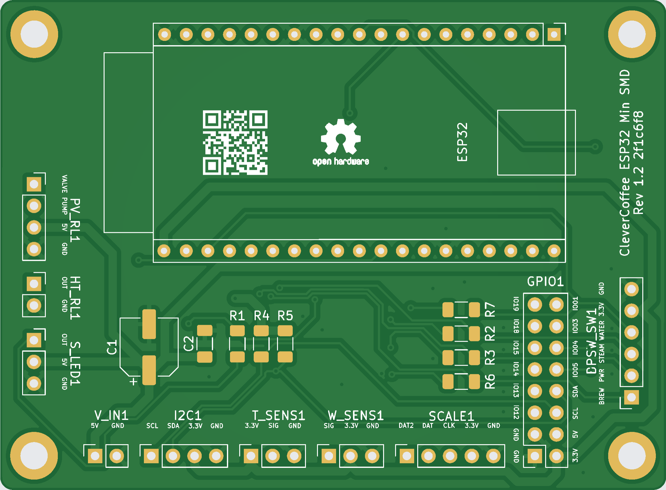
Connections on the ESP32 Minimal SMD PCB Rev 1.2
| Header | Pin Software | Pin PCB | Connection |
|---|---|---|---|
| HT_RL | PIN 2 | OUT | SSR Heating |
| T_SENS | PIN 16 | SIG | Temperature sensor |
| I2C | PIN 21 | SDA | Display and pressure sensor - Pin SDA |
| I2C | PIN 22 | SCL | Display and pressure sensor - Pin SCL |
| V_IN | - | 5V | Switching power supply (5 Volt) |
| PV_RL | PIN 17 | Valve | Relay 3-way-valve |
| PV_RL | PIN 27 | Pump | Relay pump |
| BPSW_SW | PIN 34 | BREW | Brew switch or optocoupler |
| BPSW_SW | PIN 39 | PWR | Power switch |
| BPSW_SW | PIN 35 | STEAM | Steam switch |
| BPSW_SW | PIN 36 | WATER | Hot water switch (not yet implemented) |
| S_LED | PIN 26 | OUT | Status or Temp LED |
| W_SENS | PIN 23 | SIG | Water level sensor |
| SCALE | PIN 25 | DAT2 | Scale DAT2 |
| SCALE | PIN 32 | DAT | Scale DAT |
| SCALE | PIN 33 | CLK | Scale CLK |
| GPIO | PIN 1 | IO01 | Reserved for later use, e.g. Brew switch LED |
| GPIO | PIN 3 | IO03 | Reserved for later use, e.g. Rotary encoder CLK |
| GPIO | PIN 4 | IO04 | Reserved for later use, e.g. Rotary encoder DT |
| GPIO | PIN 5 | IO05 | Reserved for later use, e.g. Rotary encoder SW |
| GPIO | PIN 21 | SDA | Reserved for later use, e.g. IO Expander |
| GPIO | PIN 22 | SCL | Reserved for later use, e.g. IO Expander |
| GPIO | PIN 12 | IO12 | JTAG Debugger TDI |
| GPIO | PIN 13 | IO13 | JTAG Debugger TCK |
| GPIO | PIN 14 | IO14 | JTAG Debugger TMS |
| GPIO | PIN 15 | IO15 | JTAG Debugger TDO |
| GPIO | PIN 18 | IO18 | Reserved for later use, e.g. Dimmer ZC |
| GPIO | PIN 19 | IO19 | Reserved for later use, e.g. Steam switch LED |
Placement and Function
All required parts and their function are listed here:
| Inscription PCB | Part | Function |
|---|---|---|
| C1 | Electrical capacitor 220 µF | Stabilization of power supply |
| C2 | Ceramic capacitor 100 nF | Stabilization of power supply |
| R1 | Resistor 220 Ω | Resistor Status LED |
| R2 | Resistor 47 kΩ | Pull down/up steam switch |
| R3 | Resistor 47 kΩ | Pull down/up power switch |
| R4 | Resistor 4,7 kΩ | Pull up i2C |
| R5 | Resistor 4,7 kΩ | Pull up i2C |
| R6 | Resistor 47 kΩ | Pull down/up brew switch or optocoupler |
| R7 | Resistor 47 kΩ | Pull down/up hot water switch |
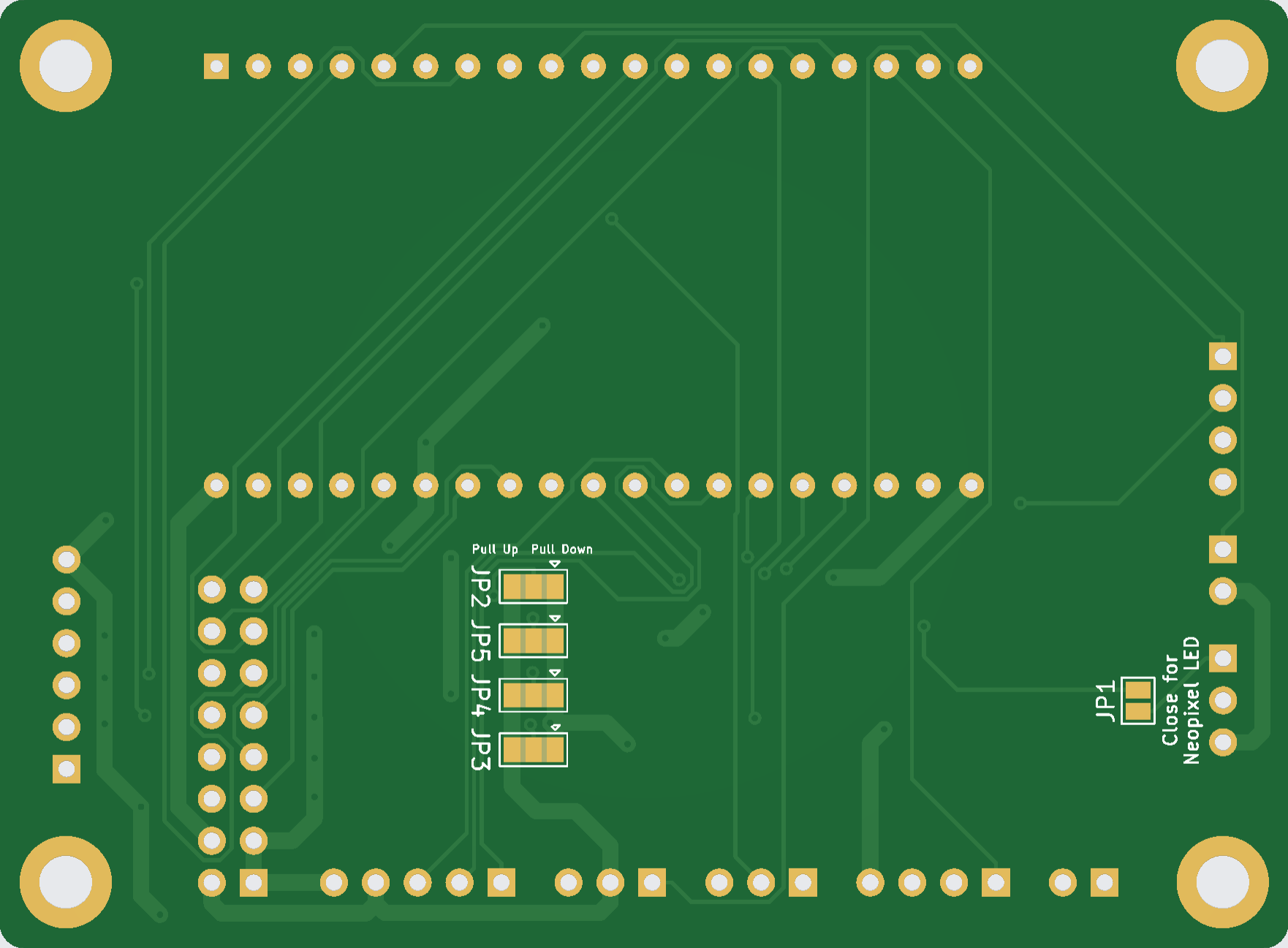
| JP1 | Solder jumper | Resistor bypass for LED when using WS1812 LED |
| JP2 | Solder jumper | Pull down or Pull up for hot water switch |
| JP3 | Solder jumper | Pull down or Pull up for brew switch or optocoupler |
| JP4 | Solder jumper | Pull down or Pull up for power switch |
| JP5 | Solder jumper | Pull down or Pull up for steam switch |
Jumper Settings
The solder jumpers allow the resistors for the Hot Water, Brew, Power, and Steam switches to be changed between pulldown and pullup configurations. These resistors define the default state of the switch input when the switch is not actuated.
The default configuration is permanently set to pulldown. To change this configuration, the PCB trace between the center pad and the pulldown pad must be cut using a utility knife or similar tool.
Afterwards, a solder bridge can be placed between the center pad and the pullup pad. When using an optocoupler for brew detection, solder jumper JP3 must, in most cases, be configured as a pullup.
Changes to Minimal SMD Rev 1.1
- Pull resistors for brew, hot water, steam, and power now bridged to GND/pulldown
Revision 1.1

KiCAD and Gerber files are available in our hardware repository: Minimal Rev 1.1
Bugs
Currently, there are no known bugs.
Connections on the ESP32 Minimal SMD PCB Rev 1.1
| Header | Pin Software | Pin PCB | Connection |
|---|---|---|---|
| HT_RL | PIN 2 | OUT | SSR Heating |
| T_SENS | PIN 16 | SIG | Temperature sensor |
| I2C | PIN 21 | SDA | Display and pressure sensor - Pin SDA |
| I2C | PIN 22 | SCL | Display and pressure sensor - Pin SCL |
| V_IN | - | 5V | Switching power supply (5 Volt) |
| PV_RL | PIN 17 | Valve | Relay 3-way-valve |
| PV_RL | PIN 27 | Pump | Relay pump |
| BPSW_SW | PIN 34 | BREW | Brew switch or optocoupler |
| BPSW_SW | PIN 39 | PWR | Power switch |
| BPSW_SW | PIN 35 | STEAM | Steam switch |
| BPSW_SW | PIN 36 | WATER | Hot water switch (not yet implemented) |
| S_LED | PIN 26 | OUT | Status or Temp LED |
| W_SENS | PIN 23 | SIG | Water level sensor |
| SCALE | PIN 25 | DAT2 | Scale DAT2 |
| SCALE | PIN 32 | DAT | Scale DAT |
| SCALE | PIN 33 | CLK | Scale CLK |
| GPIO | PIN 1 | IO01 | Reserved for later use, e.g. Brew switch LED |
| GPIO | PIN 3 | IO03 | Reserved for later use, e.g. Rotary encoder CLK |
| GPIO | PIN 4 | IO04 | Reserved for later use, e.g. Rotary encoder DT |
| GPIO | PIN 5 | IO05 | Reserved for later use, e.g. Rotary encoder SW |
| GPIO | PIN 21 | SDA | Reserved for later use, e.g. IO Expander |
| GPIO | PIN 22 | SCL | Reserved for later use, e.g. IO Expander |
| GPIO | PIN 12 | IO12 | JTAG Debugger TDI |
| GPIO | PIN 13 | IO13 | JTAG Debugger TCK |
| GPIO | PIN 14 | IO14 | JTAG Debugger TMS |
| GPIO | PIN 15 | IO15 | JTAG Debugger TDO |
| GPIO | PIN 18 | IO18 | Reserved for later use, e.g. Dimmer ZC |
| GPIO | PIN 19 | IO19 | Reserved for later use, e.g. Steam switch LED |
Placement and Function
All required parts and their function are listed here:
| Inscription PCB | Part | Function |
|---|---|---|
| C1 | Electrical capacitor 220 µF | Stabilization of power supply |
| C2 | Ceramic capacitor 100 nF | Stabilization of power supply |
| R1 | Resistor 220 Ω | Resistor Status LED |
| R2 | Resistor 47 kΩ | Pull down/up steam switch |
| R3 | Resistor 47 kΩ | Pull down/up power switch |
| R4 | Resistor 4,7 kΩ | Pull up i2C |
| R5 | Resistor 4,7 kΩ | Pull up i2C |
| R6 | Resistor 47 kΩ | Pull down/up brew switch or optocoupler |
| R7 | Resistor 47 kΩ | Pull down/up hot water switch |
| JP1 | Solder jumper | Resistor bypass for LED when using WS1812 LED |
| JP2 | Solder jumper | Pull down or Pull up for hot water switch |
| JP3 | Solder jumper | Pull down or Pull up for brew switch or optocoupler |
| JP4 | Solder jumper | Pull down or Pull up for power switch |
| JP5 | Solder jumper | Pull down or Pull up for steam switch |
Jumper Settings
The solder jumpers allow switching the resistors for the hot water, brew, power, and steam switches between pull-down and pull-up. The resistors define the state of the switch input when the switch is not actuated. The default configuration is that all jumpers are soldered to pull-down. When using an optocoupler for brew detection, in most cases solder jumper JP3 must be configured as pull-up.
Changes to Minimal THT Rev 1.6
- Resistors and capacitors implemented as SMD components
- Pull resistors for brew, hot water, steam, and power implemented via solder jumpers